
Application Background
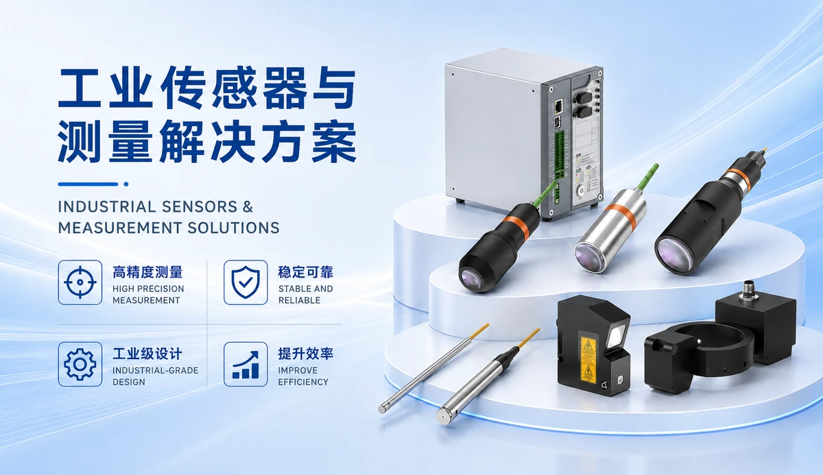
In semiconductor manufacturing, the thickness uniformity and warpage of wafer edges directly affect chip yield and subsequent packaging quality. Traditional contact measurement methods risk damaging the wafer and are inefficient. ST-P series laser displacement sensors use laser triangulation for non-contact measurement, enabling high-speed, high-precision detection of wafer edge height, thickness, and warpage, suitable for wafer processing, packaging, and testing.
Product Principle and Selection Guide
ST-P series laser displacement sensors operate on the laser triangulation principle. A laser beam is projected onto the target surface, and a CMOS or PSD detector receives the reflected light. The displacement is calculated from the position change of the light spot. For wafer edge measurement, select the model based on installation distance and accuracy requirements:
- ST-P25: Reference distance 25 mm, measurement range ±1 mm, repeatability 0.05 μm, linearity error < ±0.6 μm. Suitable for high-precision small-range wafer edge thickness measurement.
- ST-P30: Reference distance 30 mm, measurement range ±5 mm, repeatability 0.15 μm, linearity error < ±3 μm. Suitable for general wafer thickness and warpage detection.
- ST-P50: Reference distance 50 mm, measurement range ±10 mm, repeatability 0.25 μm, linearity error < ±4 μm. Balances accuracy and range.
- ST-P80: Reference distance 80 mm, measurement range ±15 mm, repeatability 0.5 μm, linearity error < ±6 μm. Suitable for larger warpage or limited installation space.
- ST-P150: Reference distance 150 mm, measurement range ±40 mm, repeatability 1.2 μm, linearity error < ±16 μm. Suitable for long-distance or large-range detection.
The sensor offers a maximum sampling frequency of 160 kHz and supports Ethernet, RS485, analog, and IO outputs, enabling integration with PLCs, host computers, or motion control platforms.
Solution Recommendations
For wafer edge thickness measurement, a dual-sensor opposed or through-beam configuration is recommended. Two sensors measure the top and bottom surfaces, and thickness is calculated from the difference. For warpage measurement, multiple sensors can be arranged radially along the wafer edge to measure height differences at various positions. Typical configurations:
- Use two ST-P30 or ST-P50 sensors mounted symmetrically above and below the wafer to measure edge thickness.
- Use multiple ST-P80 sensors evenly spaced along the wafer edge to measure warpage.
- Sensors communicate with the host computer via Ethernet or RS485 for real-time data transmission.
Installation and Commissioning Tips
During installation, note the following:
- The sensor optical axis should be perpendicular to the measured surface to avoid tilt-induced errors.
- For mirror-like or transparent wafer surfaces, adjust the installation angle or use a polarizing filter to avoid specular reflection interference.
- Keep the sensor and wafer area clean to prevent dust or moisture from affecting the optical path.
- During commissioning, use a standard wafer or calibration block for zero-point calibration and linearity compensation.
Frequently Asked Questions
- Q: The wafer surface is highly reflective, causing unstable measurements. What should I do?
A: Try adjusting the sensor installation angle (e.g., tilt 5–10°) or use a model with polarization. Sample testing is recommended to verify performance. - Q: How can I ensure accuracy when measuring wafer edge thickness?
A: Select a high-precision model (e.g., ST-P25) and ensure the sensor is firmly mounted in a stable temperature environment. Repeatability and linearity error should be confirmed per specific model. - Q: How do I connect the sensor output to a PLC?
A: ST-P series supports analog (4–20 mA or 0–10 V) and IO outputs, which can be directly connected to PLC analog or digital input modules. RS485 or Ethernet communication is also available.
Summary
ST-P series laser displacement sensors provide a non-contact, high-precision solution for wafer edge thickness and warpage measurement. Selection should be based on measurement range, accuracy requirements, and site conditions, and sample testing is recommended. The sensors support multiple output options, facilitating integration into existing automation systems.