Lithium Battery
Application of Laser Displacement Sensors in Coating Step Height and Edge Thickness Measurement for Lithium-Ion Battery Electrodes
This article introduces the application of ST-P series laser displacement sensors in the measurement of coating step height and edge thickness for lithium-ion battery electrodes. It covers inspection requirements, measurement challenges, sensor selection, implementation methods, and application value, providing a reference for online dimensional inspection solutions in battery manufacturing.
Background
This article introduces the application of ST-P series laser displacement sensors in the measurement of coating step height and edge thickness for lithium-ion battery electrodes. It covers inspection requirements, measurement challenges, sensor selection, implementation methods, and application value, providing a reference for online dimensional inspection solutions in battery manufacturing.
Pain Points
Measurement Solution
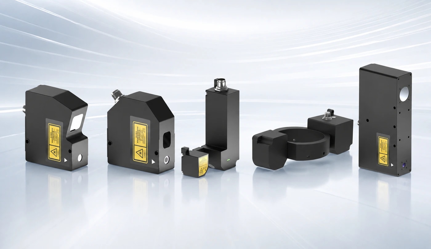
Industry Background In the manufacturing process of new energy lithium batteries, electrode coating is a critical process that determines battery performance. The height difference (the difference in height between the coating and the foil at the interface) and edge thickness consistency of the coated electrode surface directly affect the quality of subsequent rolling, winding, and cell assembly. Excessive height difference or uneven edge thickness can lead to problems such as electrode wrinkling, coating peeling, and cell short circuits. Therefore, achieving online, non-contact, high-precision detection of electrode height difference and edge thickness during the coating and rolling processes is of great significance for improving battery yield and safety. Detection Requirements * **Coating Height Difference Detection:** Measure the height difference between the coated area and the uncoated foil at the interface. A repeatability accuracy better than 1μm and a linear error less than ±5μm are typically required. * **Edge Thickness Detection:** Detect the thickness variation of the electrode edge (coating edge or foil edge) to prevent excessive edge thickness or warping, which could affect subsequent processes. * **Online Real-Time Measurement:** The detection system needs to be linked with the coating machine and rolling mill, with a sampling frequency of no less than 10kHz, supporting high-speed production lines (linear speeds up to 60m/min or higher). Non-contact measurement: Avoids damage to the electrode surface coating and adapts to the different reflective properties of copper foil, aluminum foil, and coating materials. Measurement Challenges **Interference from Highly Reflective Materials:** The strong reflectivity of copper and aluminum foil surfaces can easily cause unstable laser diffuse reflection signals, affecting measurement accuracy. **Coating Color and Thickness Variations:** Positive electrode coatings (such as NCM and LFP) are dark in color and have a rough surface, while negative electrode coatings (graphite) are black in color and have strong light absorption. Different materials exhibit significant differences in laser reflectivity. **Jitter under High-Speed Movement:** The electrode experiences mechanical vibration during coating and rolling processes. The sensor must be anti-jitter capable or employ a differential measurement method. **Installation Space Limitations:** The coating machine has a compact internal space, requiring miniaturized sensors, and the working distance must be adaptable to the site layout. **Recommended Sensor Solution:** To address the above requirements, the ST-P series laser displacement sensor is recommended. This series uses laser triangulation for non-contact measurement and features high accuracy, high sampling frequency, and multiple output modes. Based on the required detection distance and accuracy, the following models are available: Model | Reference Distance | Measurement Range | Repeatability | Linearity Error ST-P30, Detection Range 30mm±5mm, Repeatability 0.15μm The following models are available: ST-P30 and ST-P50, with a detection range of 50mm ± 10mm, repeatability of 0.25μm, and linear error < ± 4μm; ST-P80, with a detection range of 80mm ± 15mm, repeatability of 0.5μm, and linear error < ± 6μm; ST-P150, with a detection range of 150mm ± 40mm, repeatability of 1.2μm, and linear error < ± 16μm; ST-P400, with a detection range of 400mm ± 100mm, repeatability of 3μm, and linear error < ± 600μm; and ST-P450, with a detection range of 450mm ± 250mm, repeatability of 8μm, and linear error < ± 250μm. ST-P30 and ST-P50 are suitable for close-range, high-precision step difference detection; ST-P80 and ST-P150 are suitable for medium-range edge thickness detection; and ST-P400 and ST-P450 are suitable for long-range or large-area measurements. The maximum sampling frequency can reach 160kHz, meeting the requirements of high-speed online detection. Implementation Methods: Coating Step Difference Detection: Typically, a dual-probe through-beam thickness measurement or a reference surface height difference measurement method is used. Taking dual-probe through-beam measurement as an example: An ST-P series sensor is installed on each of the upper and lower sides of the electrode to measure the total thickness of the electrode; simultaneously, a reference sensor is installed above or below the same position on the electrode to measure the height of the reference surface. The coating thickness or step difference is obtained by calculating the difference between the two sensor readings. For step difference detection, a single-probe scanning method can also be used, with the sensor fixed and the electrode moving to continuously measure the height difference between the coating area and the foil area. Edge Thickness Detection: An ST-P series sensor is installed above the edge of the electrode to measure the height at the edge. Due to potential edge warping, it is recommended to measure multiple points simultaneously (e.g., inside and outside the edge) to assess thickness uniformity. The sensor installation angle should avoid perpendicular laser incidence on highly reflective surfaces; a tilt of 5°~15° is recommended to reduce specular reflection interference. Selection Considerations: Measurement Distance and Accuracy: Select the model based on the available installation space and required accuracy. For step difference detection, ST-P30 or ST-P50 are recommended; for edge thickness detection, ST-P80 or ST-P150 are recommended. Material reflectivity: For highly reflective materials such as copper foil and aluminum foil, sensors with anti-reflective properties should be selected, or the signal should be optimized by adjusting the installation angle or using polarizers. On-site testing and verification are recommended. Sampling frequency: The faster the production line speed, the higher the required sampling frequency. The ST-P series has a maximum sampling frequency of 160kHz, which can meet the needs of most lithium battery production lines. Output interface: The sensor supports Ethernet, RS485, analog, and IO outputs, which can be easily connected to PLC, host computer, or roller pressing equipment control systems. Application value: Improved yield: Real-time detection of coating step differences and edge thickness allows for timely adjustment of coating parameters, reducing defective products. Reduced material waste: Precise control of coating thickness avoids excessive or insufficient thickness, saving electrode material. Increased production efficiency: Online detection replaces offline sampling inspection, reducing downtime and enabling full inspection. Ensuring Battery Safety: Prevents internal short circuits within the cell caused by excessive step differences or edge warping, improving battery consistency. Precautions: On-site Testing: Due to significant differences in the reflective properties of electrode materials (copper foil, aluminum foil, coating), it is recommended to test with actual samples before formal deployment to confirm the sensor model and installation parameters. Environmental Factors: Dust and solvent evaporation may occur in the coating workshop. The sensor must have a certain protection rating (e.g., IP67), and the lens should be cleaned regularly. Temperature Compensation: Changes in ambient temperature may affect measurement accuracy. It is recommended to use a sensor with temperature compensation function or implement software compensation. Installation and Fixing: The sensor bracket must be stable to avoid vibration affecting the measurement. For high-speed production lines, vibration-damping installation is recommended.