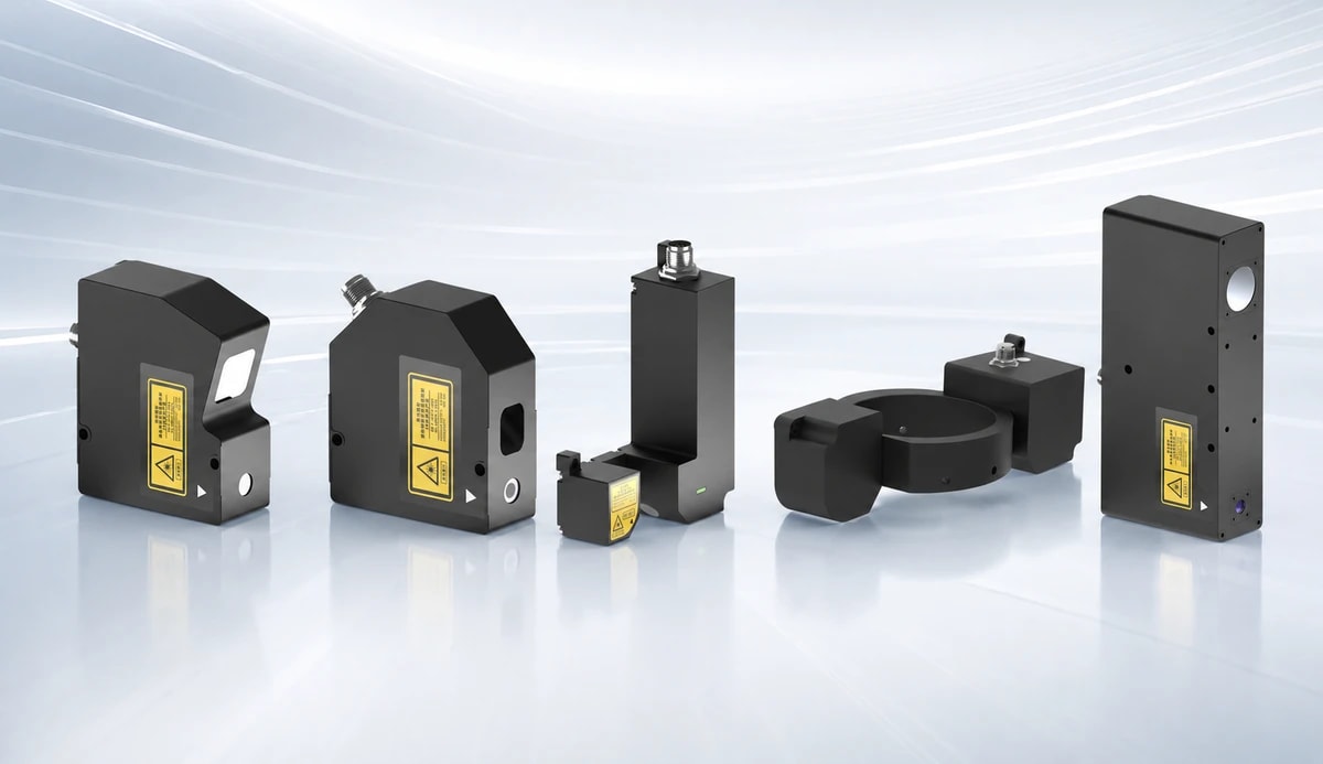
## Common Problems and Troubleshooting Suggestions for Laser Displacement Sensor Use
Laser displacement sensors are commonly used in industrial automation scenarios such as height, thickness, step difference, flatness, runout, vibration, contour, and dimension detection. Taking the ST-P series high-speed, high-precision laser displacement sensor as an example, the product supports high-precision non-contact measurement and can be connected to a host computer, PLC, or automation equipment via Ethernet, RS485 Modbus, analog signals, and I/O signals.
In practical use, the measurement effect depends not only on the sensor's own parameters but also on the installation angle, the surface condition of the measured object, exposure settings, sampling frequency, communication method, ambient temperature, and on-site wiring. Below are some common problems and troubleshooting suggestions for using laser displacement sensors.
## I. What should be considered in the installation environment of a laser displacement sensor?
Laser displacement sensors are not recommended to be installed in environments with high humidity, dust, poor ventilation, excessively high temperatures, direct sunlight, corrosive gases, strong vibration, strong impact, water or oil splashes, or environments prone to static electricity.
When installing on-site, it is recommended to pay attention to the following:
1. Avoid installation near high-voltage lines, motors, frequency converters, and other strong interference sources.
2. Power cables, signal cables, and control cables should be routed separately as much as possible.
3. If the surface of the object being measured has oil, water stains, or dust, it needs to be cleaned first.
4. Avoid obstructions, side wall reflections, or stray light within the optical axis range.
5. During high-precision measurements, maintain a stable ambient temperature as much as possible.
6. Do not expose the sensor to strong external light sources or flickering lighting for extended periods.
If dust, oil mist, or water vapor is present at the site, protective glass, air blowers, or local purification structures can be added to prevent contaminants from entering the optical path.
## II. Why do measurement data fluctuate?
Fluctuations in laser displacement sensor data are usually related to the following factors:
1. Unstable reflection from the surface of the object being measured.
2. The surface of the object being measured is too dark, too bright, transparent, or translucent.
3. The light spot falls on edges, holes, steps, or textured areas.
4. Inappropriate sensor installation angle.
5. Vibration at the site or loose tooling.
6. Dust, oil, or water stains on the protective glass or the surface of the object being measured.
7. Overexposure or underexposure.
8. Sampling frequency too high, resulting in insufficient signal quality.
9. Ambient light or stray light affecting the measurement.
When troubleshooting, it is recommended to first check the original image or peak signal. If the peak height is unstable, the peak shape is abnormal, or peaks are frequently lost, the installation angle, exposure parameters, light source power, and the position of the object being measured should be adjusted first.
## III. Will dust, oil, and water stains affect the measurement?
Yes, they will. Dust, oil, and water stains may adhere to the sensor's protective glass or the surface of the object being measured, causing abnormal laser scattering or reflection, or a weakened signal, thus causing data fluctuations.
Recommendations:
1. If there is dust on the surface of the protective glass, it can be blown away with clean air.
2. If the dirt cannot be blown away, the glass surface can be gently wiped with a soft cloth dampened with alcohol.
3. If there is oil or water stains on the surface of the object being measured, it should be cleaned before measurement.
4. If dust, oil mist, or cutting fluid are present at the site, protective structures or air blowing devices should be added.
## IV. Why do temperature changes cause data drift?
Changes in ambient temperature cause thermal expansion and contraction of the sensor's internal structure, mounting bracket, and the measured object, resulting in measurement drift. For micron-level and even submicron-level measurements, the effect of temperature is very significant.
Recommendations:
1. Preheat and stabilize the sensor and equipment before high-precision measurements.
2. Minimize exposure to direct sunlight, hot air, cold air, and heat sources from the equipment.
3. Use materials with good thermal stability for the mounting bracket.
4. For long-term online measurement scenarios, it is recommended to establish a periodic zeroing or benchmark calibration process.
5. If there are large temperature fluctuations at the site, the impact of temperature drift on the measurement results should be assessed.
## V. What if the sensor cannot connect to the host computer?
The ST-P series laser displacement sensor supports 100Mbps Ethernet communication. The default IP address usually needs to be on the same network segment as the computer's network card. If connection failure occurs, troubleshoot in the following directions:
1. After powering on, the sensor needs approximately 10 seconds to start.
2. Check if the power supply voltage is normal.
3. Check if the network cable is properly connected and undamaged.
4. Confirm that the computer's IP address and the sensor's IP address are on the same network segment.
5. Check if the computer has multiple network cards and if the software is correctly bound to the network card.
6. Use the ping command to test if the sensor's IP address is reachable.
7. If the device cannot be found through broadcast search, but the known IP address can be pinged, try point-to-point searching.
8. Confirm if multiple host computer software programs are running simultaneously, causing port conflicts.
9. If connected to a gigabit network card, ensure the network card supports 100Mbps adaptive speed.
If multiple sensors are connected simultaneously, avoid IP address conflicts. After changing the IP address, write it to Flash memory to ensure the parameters remain effective after a power outage and restart.
## VI. What should be noted regarding RS485 Modbus communication?
The ST-P series RS485 interface is a half-duplex 2-wire interface, supporting the Modbus RTU protocol. The baud rate is configurable from 9600 to 115200, and the slave address range is 1 to 247.
Common Problems:
1. A/B lines reversed.
2. Inconsistent baud rate, station number, or parity check.
3. Duplicate addresses for multiple devices.
4. Excessive cable length or significant field interference.
5. Incorrect register address or data format.
6. Excessively high polling frequency leading to unstable communication.
Recommendations:
1. First, confirm the sensor is measuring normally using a host computer.
2. Then, test the readings using Modbus tools.
3. Preferably use a baud rate of 115200.
4. When using multiple devices, ensure each device has a different address.
5. RS485 is suitable for stable data reading but not for high-speed waveform display.
6. If the customer needs to view high-speed curves, it is recommended to use Ethernet or a high-speed acquisition method via a host computer.
## VII. Why is the light source not lit or has no laser spot?
Possible causes include:
1. The software light source switch is not turned on.
2. The NPN input is configured for laser enable, but the external enable signal is not conducting.
3. Abnormal power supply voltage.
4. The sensor is in an abnormal state.
5. The light source parameters are turned off or set incorrectly.
6. The device is not properly connected or the parameters are not sent.
Troubleshooting suggestions:
1. First, confirm that the sensor power supply is normal.
2. Check if the light source switch in the host computer is turned on.
3. If using external laser enable, confirm the NPN input status.
4. Restore the default parameters and test again.
5. Do not look directly at the laser beam; pay attention to laser safety during debugging.
## VIII. How to handle overexposure or underexposure?
Exposure directly affects the peak signal quality. The data suggests setting the target exposure intensity to around 70% to 80%, which usually yields good results.
Common causes of underexposure:
1. Light source not turned on.
2. Manual exposure time too short.
3. Light power setting too low.
4. Automatic exposure time limit too low.
5. Subject color too dark or weak reflectivity.
Common causes of overexposure:
1. Manual exposure time too long.
2. Light power setting too high.
3. Automatic light power limit too high.
4. Subject surface too bright or highly reflective.
5. Peak light saturation reached.
Recommendations:
1. For materials with weak reflectivity, increase exposure time or light power appropriately.
2. For highly reflective materials, decrease exposure or adjust the angle appropriately.
3. If automatic exposure is unstable, switch to manual exposure.
4. When peak light saturation occurs, reduce light power or exposure time. 5. Observe the peak height through the original image, not just the final value.
## IX. Why Does Invalid Data Occur?
Invalid data from a laser displacement sensor usually indicates that no reliable peak value has been obtained. Common causes include:
1. The object being measured is outside the measurement range.
2. The light spot is not hitting the effective measurement area.
3. The object's reflectivity is too weak or too strong.
4. Peak saturation.
5. The peak height threshold is set incorrectly.
6. The peak sharpness threshold is set incorrectly.
7. The number of peaks does not match the expected number of peaks.
8. Transparent or highly reflective materials produce multiple interfering peaks.
9. Stray light, secondary reflections, or background light cause erroneous peak values.
Troubleshooting suggestions:
1. Check the original image to confirm the presence of clear peak values.
2. Adjust the exposure time and light power.
3. Adjust the peak height threshold, peak sharpness threshold, and minimum peak spacing.
4. For transparent objects or multi-peak scenarios, select the correct peak selection mode.
5. For measurements on opaque surfaces, prioritize using the maximum value mode.
6. For measurements within a fixed window, use the window selection mode to mask interfering peaks.
7. Check if the measurement location is within the sensor's effective range.
## X. Is a higher sampling frequency always better?
Not necessarily. A higher sampling frequency means more data needs to be read and processed per unit time. In some high-speed modes, to increase sampling speed, the number of pixels read may be reduced, potentially narrowing the available range and affecting resolution and linearity.
The documentation mentions that high-speed modes can achieve higher sampling speeds, but measurement resolution and linearity may decrease. Therefore, a balance must be struck during selection and debugging:
1. Is high-speed sampling truly necessary?
2. Is the available range sufficient for the current sampling interval?
3. Are there too many output data types?
4. Does the communication method support the corresponding data volume?
5. Does the speed of the object being measured match the sampling frequency?
For simple online dimensional measurement, the highest sampling frequency may not be necessary. However, for applications involving vibration, vibration, or rapid displacement changes, a suitable sampling frequency needs to be selected based on the cycle time and motion speed.
## XI. Troubleshooting Analog Output Abnormalities?
The laser displacement sensor supports analog outputs of 0-5V, 0-10V, ±5V, ±10V, and 4-20mA. Common causes of analog output abnormalities include:
1. Analog output is not enabled.
2. Incorrect output range selection.
3. Incorrect data source selection, for example, selecting thickness when position 1 should be selected.
4. Incorrect mapping start and end points.
5. Measured value exceeds the mapping range.
6. Current data is invalid.
7. PLC analog input type and sensor output type do not match.
Recommendations:
1. Confirm that the analog output switch is enabled.
2. Confirm that the PLC input type and sensor output type are consistent.
3. Set the mapping start and end points according to the actual measurement range. 4. Do not exceed the actual range of the sensor.
5. If the mapping range is exceeded, the output may enter the upper or lower limits or an error value.
6. If the PLC reads abnormally, first verify the analog output with a multimeter.
## XII. What if there is no response from the external trigger or NPN input?
NPN inputs can be used for external triggering, laser enable, statistical enable, and data zeroing. If external triggering is invalid, check the following:
1. Whether the NPN input is configured correctly.
2. Whether the trigger mode is edge triggering or level triggering.
3. Whether the polarity is selected correctly.
4. Whether the input pulse width meets the requirements.
5. Whether the trigger frequency is higher than the sensor sampling frequency.
6. The NPN input is low when it is on, and a falling edge from off to on.
7. Whether the NPN input is mistakenly interpreted as a PNP input.
If the software displays a trigger repetition warning, it usually indicates that the trigger frequency is higher than the sampling frequency, requiring a reduction in the external trigger frequency or an increase in the sensor's sampling capability.
## XIII. What to do about mutual interference during multi-probe measurements?
When multiple probes measure simultaneously, if the laser beam paths interfere with each other, data fluctuations or abnormal peak values may occur. The ST-P series can achieve synchronous or alternating operation of multiple probes via SYNC.
Recommendations:
1. Avoid mutual illumination of beam paths when installing multiple probes.
2. Set the same cycle time for synchronous measurements.
3. When mutual interference is significant, set alternating exposure.
4. When the SYNC cable is long or the frequency is high, it is recommended to use shielded twisted-pair cable.
5. When multiple devices are connected in parallel, it is recommended to only turn on the terminating resistor at the end device to avoid overloading the line drive.
## XIV. What should be noted for dual-probe through-beam thickness measurement?
Dual-probe through-beam thickness measurement is commonly used for measuring the thickness of non-transparent materials. Common problems include:
1. The two probes are not aligned.
2. The measurement range of the two probes does not cover the measured object.
3. The mounting structure on both sides is unstable.
4. The two probes are not sampling synchronously. 5. The object being measured is tilted or vibrating.
6. The thickness calibration parameters are incorrect.
Recommendations:
1. First, confirm that each probe is stable when measuring individually.
2. Then adjust the relative position and optical axis of the two probes.
3. Use the SYNC synchronization or alternating exposure function.
4. Calibrate the thickness formula and MATH parameters.
5. When the object being measured moves, consider the positional difference caused by the sampling interval and movement speed.
## XV. Will the measurement range change after zeroing?
Software zeroing or offset correction will not change the actual physical measurement range of the sensor.
For example, if the actual range of a probe is fixed, setting an offset only changes the displayed value; the actual measurable distance is still limited by the sensor's physical range. Therefore, if the object being measured moves beyond the actual range after zeroing, invalid data or a red over-range warning may still appear.
Recommendations:
1. Before zeroing, confirm that the object being measured is near the middle of the range.
2. Do not use the offset function to replace the correct installation distance. 3. Before conducting large-scale measurements, confirm that the actual travel distance is covered.
4. Be cautious when modifying correction factors; it is not recommended to change the factory calibration factors unless absolutely necessary.
## XVI. How to read sensor indicator lights?
Different models may have slight differences, but generally, the measurement range can be determined by the status lights:
1. Flashing green light: Reading is in the center range.
2. Solid green light: Reading is in the middle range.
3. Solid yellow light: Reading is within the full range but near the edge.
4. Solid red light: Reading is outside the full range.
5. Flashing red light: Light source switch is off.
During on-site debugging, the status lights can help quickly determine whether the measured object is within the reasonable measurement range.
## XVII. Why are the desired fields not present when saving data?
On the host computer software, only data selected in "Output Data Selection" will be uploaded, displayed, and saved. Output data typically includes timestamps, sampling numbers, position 1, position 2, thickness, statistical values, peak height, laser power, exposure time, warning messages, and temperature.
Recommendations:
1. Confirm the output data selection before saving data.
2. Do not select unnecessary fields to avoid excessive data volume.
3. During high-speed sampling, too many output fields will affect communication and saving efficiency.
4. If only displacement data is needed, prioritize saving the timestamp, sampling number, and position value.
## XVIII. Summary of On-site Troubleshooting Recommendations
When a laser displacement sensor exhibits measurement abnormalities, troubleshoot in the following order:
1. First, check the power supply: Confirm that the voltage, current, wiring, and grounding are normal.
2. Then, check the connections: Confirm the IP address, network cable, and port.