## Common Problems and Troubleshooting Suggestions for Using Spectral Confocal Displacement Sensors
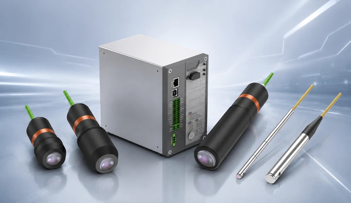
Spectral confocal displacement sensors are commonly used in high-precision non-contact displacement measurement, transparent material thickness measurement, step difference detection, contour detection, and flatness detection. Compared to ordinary laser displacement sensors, spectral confocal sensors have better adaptability to materials such as mirrors, transparent bodies, thin films, glass, and wafers. However, in practical applications, the installation angle, refractive index setting, light source status, exposure parameters, measurement range, and environmental stability all affect the final measurement results.
This article summarizes common problems encountered in field use and provides troubleshooting suggestions based on spectral confocal displacement sensor parameter data and common problems, for engineers to refer to during selection, installation, and debugging.
## I. What to do if the controller cannot connect?
Common connection methods for spectral confocal controllers include Ethernet, USB, and RS485 Modbus. If the host computer cannot connect to the device, troubleshoot in the following directions:
1. Check if the controller is powered on normally and if the power supply voltage is within the allowable range of DC24V.
2. When connecting via Ethernet, ensure that the computer's network card IP and the controller's IP are on the same network segment.
3. The default controller IP is usually 192.168.0.10. You can test the connectivity using the ping command on your computer.
4. Check the network cable for damage, short circuits, open circuits, or poor connections.
5. Confirm that multiple host computer software programs are not open simultaneously on the computer to avoid port congestion.
6. When connecting via USB, check if the USB cable, USB port, and COM port are being used by other software.
If the device can ping but the software cannot connect, further checks are usually needed on the port, software version, controller IP configuration, and firewall settings.
## II. What are the reasons for the light source not lighting up?
Spectral confocal measurement relies on a stable light source and fiber optic transmission. If the light source is not lit or there is no measurement signal, check the following steps:
1. Check if there is light output from the controller's fiber optic interface.
2. Re-plug the fiber optic cable, ensuring it is fully inserted and the latch is locked.
3. Check the optical fiber for damage, excessive bending, or end-face contamination.
4. Check if the fiber optic interface at the probe end is loose.
5. Confirm that the probe dust cover has been removed.
6. Confirm in the software that the light source switch is on.
7. For dual-channel controllers, also confirm that the corresponding channel is enabled.
8. Check if the trigger source is set to internal trigger; if it is set to external trigger but there is no external signal, it may not collect data correctly.
During on-site debugging, it is recommended to first confirm whether light is emanating from the controller end, and then check the status of the optical fiber and probe end. This makes it easier to locate the problem.
## III. How to set the exposure time and sampling frequency?
The exposure time needs to be less than the sampling interval. The device must complete exposure, acquisition, and processing within one sampling cycle. If the exposure time is too long, the actual sampling speed will be affected.
Simply put:
Sampling interval = Exposure time + Data processing time
Therefore, the higher the sampling frequency, the shorter the allowable exposure time is usually. If the object under test (DUT) has low reflectivity, the exposure time may need to be increased, but the sampling rate will decrease. For high-speed measurements, the exposure time needs to be controlled, and the returned signal strength must be sufficient.
Recommendations:
1. For highly reflective materials, exposure can be appropriately reduced to avoid signal saturation.
2. For low-reflective materials, exposure can be appropriately increased to enhance the peak signal.
3. During high-speed online detection, priority should be given to confirming whether the sampling interval, exposure time, and output method are matched.
4. RS485 Modbus mode is generally not suitable for high-speed waveform acquisition. If a higher sampling rate is required, Ethernet or a high-speed data interface of the controller should be considered first.
## IV. Why is Dark Calibration Necessary?
Dark calibration is used to subtract the influence of system background light and light reflected from within the optical fiber.
After the light source is emitted from the controller, it is transmitted to the probe via optical fiber and then reflected back to the controller from the surface of the DUT. During this process, some light may not originate from the actual surface of the DUT, but rather from the optical fiber or background signals within the system. Dark calibration allows the acquisition of background signals even without a DUT, which can then be subtracted from the actual measurement image, thereby reducing background interference.
It is recommended to recalibrate in the following situations:
1. After replacing the probe or fiber optic cable.
2. After significantly adjusting the light source intensity or exposure parameters.
3. When there are significant changes in ambient light.
4. When the measurement data is unstable for a long period or when there is significant background noise.
5. Before high-precision thickness measurement or measurement of transparent objects.
## V. What to do if the thickness measurement of transparent objects is inaccurate?
When measuring the thickness of transparent materials, the refractive index setting is crucial. When measuring the thickness of transparent objects using spectral confocal methods, it is not simply a matter of using "distance 1 - distance 2" directly as the thickness; it is also necessary to calculate it in conjunction with the material's refractive index.
Common problems:
1. Incorrect refractive index setting, resulting in a thickness that is too large or too small.
2. The object being measured is not a single material; it contains coatings, adhesive layers, or multilayer film structures.
3. The surface of the object being measured has curvature, which does not meet the assumptions of a planar model.
4. The object being measured is tilted or the installation angle is unstable.
5. The difference in refractive index at different wavelengths is not properly compensated. Recommendations:
1. If the material's refractive index is known, it should be correctly set in the software.
2. If the refractive index is unknown, first measure the actual thickness using a micrometer or other standard methods, then adjust the refractive index parameter to ensure the near-end, middle, and far-end measurements match the true thickness.
3. When measuring the thickness of multi-layer materials, confirm that the software and controller support corresponding peak recognition and multi-layer thickness calculation.
4. For transparent glass, thin films, wafers, coatings, etc., prioritize confirming whether the peak values are clear and stable.
## VI. What do Distance 1, Distance 2, and Thickness Values Mean?
In spectral confocal measurements, the distance value is usually the relative position of the measured object with respect to the probe reference distance.
For non-transparent objects, the spectral image usually has only one good peak; the converted result of this peak can be used as Distance 1.
For transparent objects, the spectral image may show two or more peaks. Common understandings are as follows:
| Data Item | Meaning |
|---|---|
| Distance 1 | Distance from the probe to the surface of the object being measured closest to the probe |
| Distance 2 | Distance from the probe to the surface of the object being measured furthest from the probe |
| Thickness | Thickness value calculated based on distance 1, distance 2, and the material's refractive index |
Therefore, distance 1 minus distance 2 does not necessarily equal the actual thickness. For transparent materials, the refractive index must be considered when measuring thickness.
## VII. What does -2147 mean in measurement data?
When the output data is -2147, it usually indicates invalid data. Common reasons include:
1. The object being measured is outside the probe's measurement range.
2. The peak signal is too weak or cannot be recognized.
3. The light reflected from the object being measured failed to effectively return to the probe.
4. The surface tilt angle exceeds the probe's measurable angle.
5. Deep holes, obstructions, or structural interference block the light path.
6. The software peak selection mode is incorrect.
If invalid data is encountered, it is recommended to first check the original spectral image to confirm the presence of stable, clear, and reasonably positioned peaks.
## VIII. How to Debug a Dual-Probe Through-Eye Thickness Measurement?
Dual-probe through-eye thickness measurement is commonly used for thickness measurement of opaque materials, thin sheets, wafers, metal sheets, and films. The key to debugging is ensuring the optical axes of the two probes are aligned and the distance between them is stable.
Recommended Steps:
1. First, adjust the relative distance between the two probes.
2. Place a piece of white paper between the two probes so that the light spots from both probes are focused on the paper.
3. Check the spectral images on both sides and coarsely adjust until both channels have good peak values.
4. Adjust the X/Y directions until the two light spots visibly overlap.
5. Continue to observe the original image while fine-tuning the X or Y direction of one probe.
6. When the two peaks in the image gradually merge into one, the alignment is basically complete.
If the alignment is poor, problems such as thickness measurement fluctuations, data deviations, and increased thickness volatility may occur.
## IX. Will alternating exposure with dual probes introduce errors?
Alternating exposure with dual probes introduces an inherent time difference. The sampling time interval between the two probes is approximately half the sampling interval.
For example, with a sampling interval of 200 μs, the sampling time difference between the two probes is approximately 100 μs. If the lateral movement speed of the object being measured is 30 m/min, the lateral position difference between the two probes will be approximately 0.05 mm.
This lateral position difference does not necessarily directly cause thickness error. For relatively flat materials such as straightened films, flat glass, and steel strips, the impact is usually small; however, if the surface of the object being measured has significant undulations, ripples, or vibrations, the lateral position difference may translate into a difference in thickness readings.
Recommendations:
1. Pay attention to the sampling interval and movement speed in high-speed motion scenarios.
2. For materials with large surface undulations, reduce the speed or improve sampling synchronization.
3. For scenarios sensitive to thickness fluctuations, dynamic sample verification should be performed.
## X. In which scenarios can spectral confocal measurements be impossible?
While spectral confocal microscopy is suitable for high-precision non-contact measurements, it is not stable in all scenarios. The following scenarios require special attention:
1. The tilt angle of the mirror material exceeds the probe's allowable measurement angle.
2. Deep holes, slits, or obstructive structures prevent reflected light from returning to the probe.
3. Microstructures on the surface of the object being measured, similar in size to the light spot, cause abnormal reflected light direction.
4. The object being measured is smaller than the light spot size, for example, a structure with a diameter of approximately 1 μm; such structures are generally not directly measurable.
5. Matte, semi-transparent materials may cause broadening of spectral peaks, affecting peak positioning accuracy.
6. Thickness measurements of transparent objects with large surface curvature may be inaccurate.
7. The object being measured exceeds the probe's upper and lower measurement range limits; even if a peak is detected, no valid measurement data can be output.
Before selecting a probe, the material of the object being measured, its surface condition, tilt angle, measurement range, light spot size, and installation space should be confirmed.
## XI. What causes data drift after a period of measurement?
When measured values change slowly over time and the deviation exceeds the nominal linearity range, it is usually a drift problem. Common causes include temperature effects and changes in mechanical structure.
### 1. Temperature Effects
Probes, controllers, and mounting structures are all affected by temperature, undergoing thermal expansion and contraction. Controllers and probes themselves have temperature drift specifications, and fixtures, supports, and platforms can also experience thermal deformation.
For example, aluminum has a high coefficient of thermal expansion; in high-precision measurements, changes in support length can introduce micron-level errors. Therefore, in high-precision measurements, it is crucial to consider not only the sensor itself but also the thermal stability of the mounting structure.
Recommendations:
1. Operate the probe and controller in a constant temperature environment whenever possible.
2. Preheat the equipment and mechanism for a period of time before measurement to allow them to stabilize.
3. For high-precision applications, prioritize support structures with better thermal stability, such as steel or marble.
4. Avoid environmental changes such as strong airflow, heat sources, and direct sunlight.
### 2. Mechanical Drift
After installation, stress release may occur in the fixture, fine-tuning stage, flexible pads, and locking structure, causing slow changes in measured values. Most mechanical drift will stabilize within tens of seconds to minutes, but it still needs to be monitored for high-precision measurements.
Recommendations:
1. Ensure the locking structure is reliable after probe installation.
2. Avoid using easily deformable flexible materials to fix the probe.
3. Allow the mechanical structure to stabilize before measurement.
4. For micron-level measurement scenarios, it is recommended to establish a regular zero-point calibration process.
## XII. What are the differences between repeatability, longitudinal resolution, and static noise?
These three metrics are easily confused:
| Metric | Meaning |
|---|---|
| Repeatability | Consistency between measured values when measuring the same point multiple times |
| Longitudinal Resolution | The smallest displacement change the sensor can resolve |
| Static Noise | The amplitude of the reading's fluctuation when measuring a stationary object |
In practical applications, if the displacement change is less than the static noise, it may be overwhelmed by noise and difficult to reliably distinguish. Therefore, when evaluating sensor accuracy, one should not only look at a single parameter, but also consider repeatability, linearity, temperature drift, sampling frequency, and on-site installation conditions for a comprehensive judgment.
## XIII. What are the effects of spectral peak broadening?
Under normal circumstances, spectral confocalization will convert distance based on the clear peak position. When the peak broadens, the peak positioning accuracy will decrease, and the measurement stability will also deteriorate.
Common causes of peak broadening:
1. The tilt angle of the mirror material is close to the probe's measurement angle limit.
2. The effective light-gathering aperture of the probe becomes smaller, and the confocal characteristics deteriorate.
3. The object being tested is a matte, semi-transparent material, such as matte resin or white ceramic.
4. Light entering the material creates a halo, causing the peak to broaden.
5. Strong surface scattering results in an unclear reflection interface.
When encountering peak broadening, it is recommended to adjust the probe angle, exposure time, and light source intensity. If necessary, replace the probe with a model more suitable for the material.
## XIV. How fast can Modbus readout speed be?
Spectral confocal technology supports RS485 Modbus RTU communication, but Modbus is not suitable for high-speed waveform acquisition. The actual sampling rate depends on the amount of data read, the baud rate, and the host polling method.
At a baud rate of 115200, if using Modbus Poll testing and reading a large amount of data, the scan time can be set to within approximately 5 ms. To ensure reliable transmission, it is recommended that the Modbus sampling rate not exceed 100 Hz.
Recommendations:
1. Only read necessary registers to reduce the amount of communication data.
2. Set the baud rate to 115200 whenever possible. 3. If the customer needs to view high-speed waveforms or contour changes, RS485 is not recommended as a primary method.
4. For high-speed data acquisition, Ethernet, SDK, or a high-speed data method supported by the controller are recommended.
## XV. Summary of On-Site Usage Recommendations
To ensure stable measurement by the spectral confocal displacement sensor, the following points are recommended:
1. When selecting a sensor, confirm the measurement range, reference distance, spot size, repeatability, linearity error, and the material of the object being measured.
2. When measuring the thickness of transparent objects, the refractive index must be set correctly.
3. During installation, ensure the angle between the probe and the object being measured is within the allowable range.
4. When using dual probes for thickness measurement, ensure proper optical axis alignment.
5. Before high-precision measurements, it is recommended to preheat and allow the mechanical structure to stabilize.
6. When data fluctuations, invalid values, or drift occur, first check the original spectral peak value.
7. Verification is required in advance for scenarios such as deep holes, obstructions, strong tilt, very small microstructures, and matte semi-transparent materials.
8. RS485 is suitable for stable data reading, but not for high-speed waveform display.
9. When measuring the thickness of dynamic materials, sampling frequency, movement speed, and surface undulations must be considered simultaneously.
10. If different probe models show differences in measured thickness, the installation perpendicularity, calibration status, curvature, and material model should be checked.
## Conclusion
Spectral confocal displacement sensors are suitable for high-precision, non-contact measurement of transparent and specular materials. However, the actual performance depends not only on the sensor parameters but also on the surface of the measured object, installation method, refractive index setting, light source status, sampling parameters, and the on-site environment. Engineers should consider both the original spectral image and measurement data during selection and commissioning.